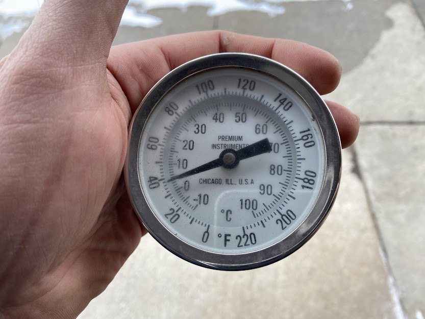
During an investigation of the collapsed electrical shop, I located this beautiful specimen. It is still in it’s original box and seemingly never opened after 20 years in a natural landfill, and some years even older than that. It not only works but seems quite accurate when compared to another thermometer. It would not be prudent to do anything besides find a way to display this beauty!

Normally I’d hesitate to remove such an object from the site, which is devoid of any specific history related to the plant, or even the industry. Thermometers like this are general purpose and used all over the world in various applications, most of which have nothing to do with coke making or even steel making. I chose to not only take this thermometer, but to build something to display it for two reasons. First being its immaculate condition, brand new in box for two decades. I went back in the day after I found it to try to get the remains of the frozen box (which I had to tear to extract it’s contents, the frozen water had fastened it to a wooden crate), hoping I could scan it but it was devoid of a label. The second being the extreme personal risk I stupidly invoked by crawling until this dangerous overhand with constant threat of a pending collapse. To display this thermometer is as much a testament to the plant as it is to the extent I needed to go to attain it.
The back of the dial has about 3/4″ of threads – I knew these had to be tapered (NPT) and I also knew I could use these as the basis of my mount. So out came the digital calipers to try to measure the size.

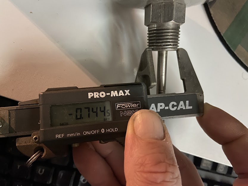
So 1/2″ it is. My plan was to screw it into a pipe flange, then mount the flange to wood so it could stand up and be readable. A simple 90 degree joint of two pieces of stock would work but the weight of the thermometer and the flange would push the center of gravity so far forward it would surely tip over. I though I could cut the joint between the upright section and base on a bias to over come this, so it would ‘lean back’. Time for a very crude drawing to illustrate:
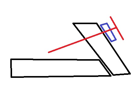
I figured even 10 degrees off of square would provide sufficient tilt to keep this upright despite it’s weight though I’d have to toy with the length of the ‘foot’ and the upright. In the midst of this my friend and Acme legend Steve Buckner had another idea which he sent me via SMS.

I dismissed this initially as overwrought but like a bad pop song, it soon crept into my psyche and I could think of nothing else. I especially loved the last sentence – I admire all the things I have brought back and restored. I never thought about that word to describe what I am doing, but that is dead on.
I had one small issue however, with the wooden base and told Steve as much in a continuing discussion via email:
- I don’t have a hole saw 6″, I think my biggest is 3″. I don’t want to buy a bigger one and use it once. The flange I am looking at it is 3 1/2″ OD so even a 4″ would potentially work but I don’t have that either. And I think more wood should show anyway
- I hesitate to cut into that door, it would pain me too greatly. That being said, my initial thought when I discovered it was to take the whole door, but…. (see below)
- the paint is peeling pretty badly. So I think it wouldn’t hold up very long on my desk.
However, ironically I had been thinking of using some reclaimed wood from the plant for another project. If I could bring a chunk back with me, I could cut out a circle with a jigsaw (which I already own, unlike the pricy hole saw). But that would have to wait until I could get back to the plant, as all this mania came after I had left the plant Saturday evening. So in the meantime, I went shopping on McMaster Carr for fittings.
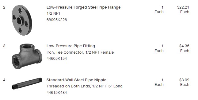
Flanges aren’t cheap – there was an aluminum one for $17 but I decided the extra $5 was worth it so I could get all dark colored fittings and not an offensively shiny flange.
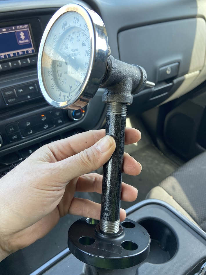
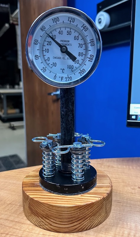
I brought it with me in the truck so I could put the whole thing together in the Will Call parking lot. It already looks great…but wait, there’s more!
Steve’s recommendation that I build a base for this unit is a great idea. There is the aesthetic value, plus the fact it would be made from real Acme wood. But the flange actually has a smaller ‘flange’ on the bottom, so technically it does not sit flat and might one day endure a tip over. So I started to kick around ideas on how or what to fabricate when I decided to invoke my friend Mike who is a far greater craftsman that myself, who also has a workshop filled with proper woodworking tools.
I told him I would get him 2x12x18 to fabricate a 6″ circle from. Beyond that I largely left it up to him. For hardware to mount the base to the flange, I went with 1/2″ bolts and nuts (for the 5/8″ holes). I had to wait a week to procure the hardware, since I could not be entirely sure of the stock thickness. A 2×12 today is only 1.5″ thick, but the age of this wood may put it from the era of REAL dimensional lumber. So I picked out two lengths of bolts on McMaster and waited for the weekend. The plan being that I would get the lumber Saturday morning, measure the thickness and pull the trigger on a Will Call order for Monday morning. By EOD Monday the stock, flange and hardware would be en route to Mike’s home in Louisville.
I spent a Saturday morning investigating the collapsed electric shop, as I have access to lots of lumber there. But would not find anything thicker than 1.5″. Eventually I moved over to the collapsed north/south ends of the storehouse but the wood there was also suitable, but nothing special.
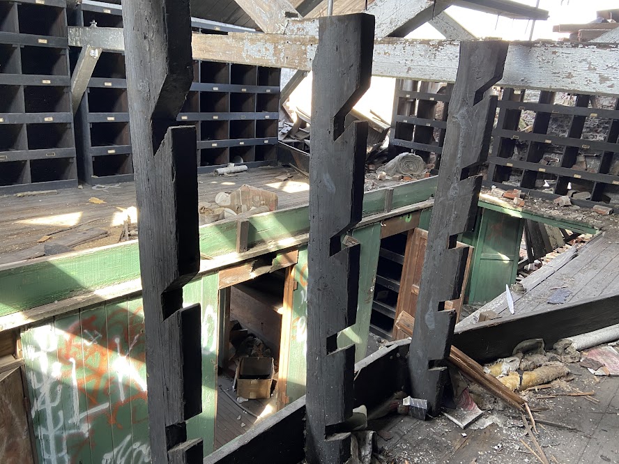
Finally, on the mezzanine in the north end of the building, I found some ‘racks’ that had been built by notching out some boards. Presumably to hold pipes or shafts or some other long material. They measured at 2″ thick! They were fastened in place, but with only a couple nails. One went into the end grain at the top, connecting it to a horizontal strut to keep the ‘racks’ from tipping over. I used another board I found as a hammer to tap upwards and that came out pretty quickly. The others (not sure if there were 1 or 2), attached it to the toe board at the floor level. I just wrenched the board by hand which bent the nail until it came out. It came out with a lurch – luckily I didn’t throw myself overboard but I did drop/throw the lumber downstairs. This certainly proved its strength as it came out unscathed.
I had half-planned to saw whatever I brought back into manageable chunks so I could bungee it to the rear rack of my bike for the ride back to Hegewisch. I decided I did not want to do that, I knew this would need to be planed so I figured the best thing was to leave it whole. So I carried it up to the driveway next to the gatehouse, biked back to Hegewisch, then returned with my truck. This marks only the second time I have ever removed anything from the plant via vehicle (the other was my standing desk).
I got the board to Mike (he actually had to make a trip to Chicago) and a few weeks later when he had time he got started. He cut the end of the board off so we could have a look at the grain and general condition of the material (it is pained with some kind of industrial coating which prevents you from seeing the lumber itself). Good news – it looked healthy.
Fast forward a number of months – Mike was unable to finish the project. What he did do was to cut a workpiece into about a 5.25″ round. This left the rest to me.
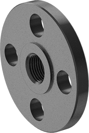
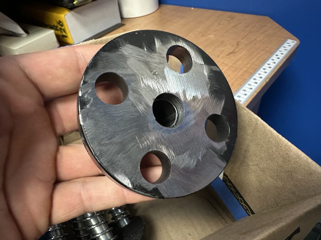
The first thing I did was to take an angle grinder to the bottom of the flange, it has a bit of a ‘nub’ in the middle which must be used when it would interface with another flange or a gasket. It made the flange not sit flat so it had to go. I routing out an area on the workpiece (wouldn’t have to be that accurate since it would be covered up) but angle grinders are just too much fun.
After that I got to drilling. I did some test holes in a piece of scrap. I used a 5/8″ spade bit but the entire pin pulled through the hole. I would need to use a 1/2″ bit (which I did not have, but would be willing to run and purchase if necessary) which would keep the pin from pulling through but also be a very tight fit. So I had to use a washer – which meant I needed to countersink from the bottom. This created a new issue – the workpiece was already not thick enough to put any compression on the spring so I’d have to remedy that later. So I used a 1″ forstner bit and again did a few test holes in a piece of scrap. Besides his band saw for cutting the round, I was relying on Mike to use his drill press to drill these holes square. I’d have to do them by hand and just do my best.

I had to go back and deepen the countersinks a few times but eventually got it all together. As expected, the lack of compression on the springs due to the lack of thickness in the workpiece was a problem. This was where I started to think, “maybe I should just use a nut/bolt”. But that would be a cop out!
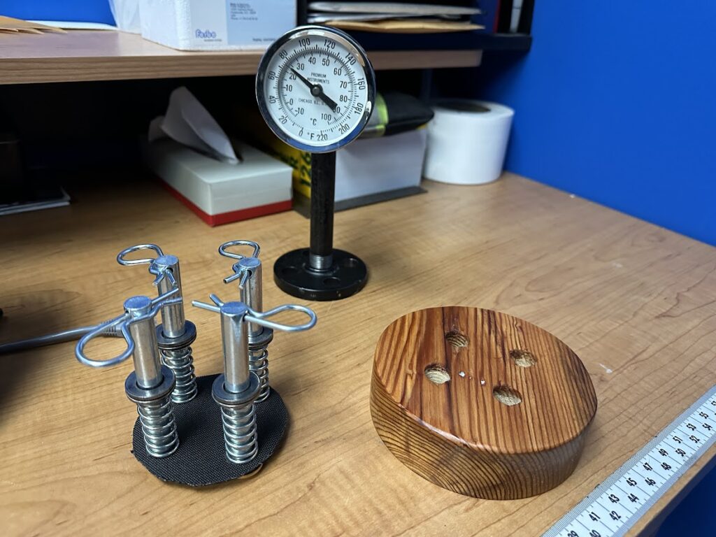
So I cut a piece of rubber material I had (which had the added benefit of being black, so you would never be able to see it). I cut it into a circle the same size as the flange, then punched out the 4 holes with a hammer. This got me VERY close but still not close enough. However, I was using my washers inside the base, which I had not planned to do. So I grabbed some additional washers. After doubling them up, I got compression. I may try to find longer springs or thicker washers (or spacers) but for now this works. The doubled up washers is only in my head, you can’t tell it is two unless you look very closely. If I do get longer springs, I can even ditch the rubber shim, then again no one can see it, so what’s the use? I am also maybe thinking about trying a 4″ nipple, I need to be clear of the pins/springs, not sure if it might be a bit more elegant if it was shorter.
After that I sanded the base with 5 grits (120/180/240/320/400) then gave it a couple coats of linseed oil. At long last, this project is done!